
ST Link V2 Upgrade
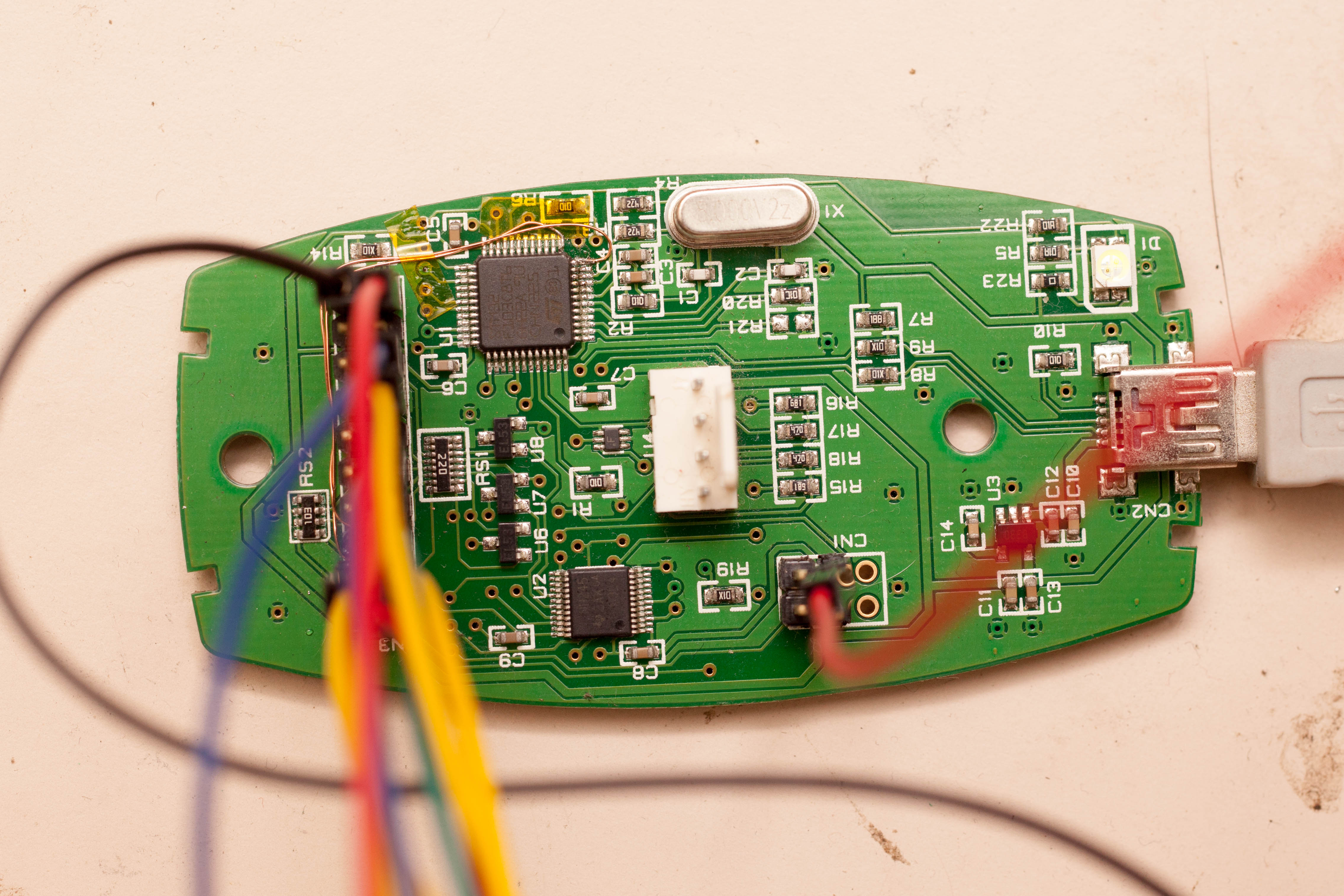
Fig 1 - Modified PCB
Intro
ST put out a video ages ago showing some mods to their low cost debugger. They added some LEDs and a 5V output, not very useful. Here's some tips for turning your ST Link into a general purpose ARM debugger while still maintaining the original looks and function of the device.
To get the new functionality, we need to flash the debugger itself with new firmware. An open source project called Black Magic Probe exists which gives us a choice between SWD or JTAG, no need to install drivers (BMP is a standard serial device), painless build and reload workflow on linux and optionally UART.
Prerequisites
- ST Link V2 debugger
- Another ST Link or a discovery board
- Soldering iron and enameled wire
- A working ARM GCC install
- Various other linux command line tools that are unavailable on your distro or fail to build just for you
Building
Luckily the BMP firmware has few dependencies and the ones it has are submodules with the make file doing all the work
(´ ・ω・` )
git clone git@github.com:blacksphere/blackmagic.git
cd blackmagic
git submodule init
git submodule update
make
cd src
make clean
make PROBE_HOST=stlink
You shouldn't get any warnings or errors and have two new files: blackmagic.bin and blackmagic_dfu.bin.
ST Link V2 SWD Header
You'll want to solder a header to CN1 on your target debugger, the pin out is provided below.

Fig 2 - CN1 Header
Now connect the two debuggers together.
Flashing
To flash we need to use either the official ST tool or a combination of texane stlink util to do a full erase and OpenOCD to unlock the flash region. Neither of these tools will be used after flashing is complete.
openocd -f interface/stlink-v2.cfg -f target/stm32f1x_stlink.cfg -c "init" -c "halt" -c "stm32f1x unlock 0" -c "shutdown"
st-flash erase
st-flash --reset write blackmagic.bin 0x8002000
st-flash write blackmagic_dfu.bin 0x8000000
If any of the flashing steps fails, remember we don't have a NRST signal so you'll need to manually reset the device.
If all went well you can now connect the debugger via USB and you'll see two new devices under /dev/. The first is the debug target itself, the second is a serial port we can use to communicate with the target.
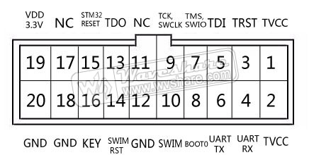
Fig 3 - Debug Header
The debugger pin out remains the same as the original however the bottom row except pin 2 are connected to ground. Next we'll make 6 and 4 actually function as UART ( ´_ゝ`)
Adding UART
Take a knife to the back of the PCB, cutting the connection from the ground plane to pins 6 and 4.

Fig 4 - UART
Run two wires from U1 pin 12 and 13 to 6 and 4 respectively.

Fig 5 - Don't burn your fingers
Try not to forget this is a direct CPU connection so RS232 will almost certainly not work.
Congratulations you now have a self contained debugger and serial port that will work with a heap of different ARM platforms.